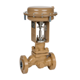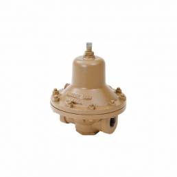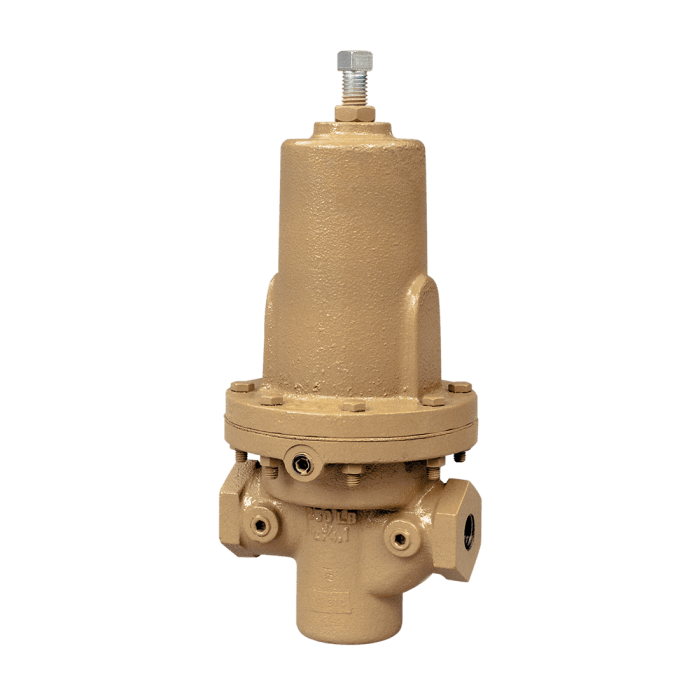
Differential reducing regulator DA2 CASHCO
The Model DA2 is a differential reducing regulator used to maintain a constant pressure differential between a fluid loading pressure (PLOAD) piped to the spring chamber and the regulator’s outlet pressure (P2 ). In the Model DA2 the P2 pressure is higher than the PLOAD (Positive Bias). The amount of bias or differential pressure (∆PDiff) is controlled by the user adjustable setting of the range spring in the spring chamber.
The regulator uses a flow-to-open, cage balanced trim. The diaphragm is isolated from the fluid flow path by a balancing piston, which allows the user to specify either internal or external sensing of the P2 pressure.
Key Features:
- Versatile: Four basic materials and multiple trim material combinations to select from.
- Tight Shutoff: Multiple composition materials provide Class IV or VI inboard leakage rates. Designed as a soft-seated valve.
- Capacity: Highest in the industry. Allows smaller body sizes than competitors in majority of applications.
- Pressure Drop: Highest in the industry when coupled with high flow capacity.
- Trim Design: “DO-ALL” trim design provides FTO and pressure balancing for higher inlet pressure. Results in unmatched sensitivity and stability. Internals are cage-contained within easily removable quick change trim.
- Rangeability: Basic valve gives outstanding rangeability due to close tolerances, balanced trim, and a broad range of elastomeric diaphragms and soft seats. Can be as high as 1000:1.
- Heavy-Duty Guiding: Both top and bottom guided to maintain stability and increased diaphragm life.
Technical Data:
| Failure Position: | DA2 fails open on loss of P1 or P2 pressures |
| Line Sizes |
1/2″ (DN15) 3/4″ (DN20) 1″ (DN25) 1-1/4″ (DN32) 1-1/2″ (DN40) 2″ (DN50) 3″ (DN80) 4″ (DN100) |
|
End Connections
|
Standard: Female NPT (screwed). ASME Flanged: 125#, 150#, 250#, 300#, 600#; DIN Flanged: PN16, PN25, PN40; (Integral Flanged Body unless listed under Opt.-30) Opt-31: British Standard Pipe Threads Opt-32: Schedule 80 Extended Pipe Nipples. Opt-34: 14″ Face to Face Flange Dimension. Opt-41: Extension Tube Ends. |
|
Differential Pressure
|
1/2″–1″(DN15–25): 1 to 200 psid (.07 to 13.8 Bard) 1-1/4″–1-1/2″ (DN32–DN40): 1 to 125 psid (.07 to 8.6 Bard) 2″ (DN50): 1 to 90 psid (.07 to 6.2 Bard) 3″–4″ (DN80–100): 1 to 125 psid (.07 to 8.6 Bard) NOTE: Ranges may be limited by diaphragm selection. |
| Inlet Design Pressure | 10–3705 psig (.69-255 Barg). |
| Material Combinations: |
Body / Spring Chamber DI/DI BRZ/BRZ * BRZ/SST CS/DI BRZ/DI SST/DI CS/CS BRZ/CS SST/CS SST/SST * Through 2″ (DN50) body size only.
|